- #Lcd ds3231 arduino uno pinout how to#
- #Lcd ds3231 arduino uno pinout serial#
- #Lcd ds3231 arduino uno pinout code#
- #Lcd ds3231 arduino uno pinout plus#
In the next few steps we’ll connect the display further to the Arduino to let the arduino communicate with the LCD screen and put some characters on it.

If your display looks like this, you’re doing fine: You can finetune this setting when we’ve got characters on the display later. Of you don’t see them, turn the pot meter slowly from left to right to adjust the contrast. When you power up the Arduino now, you will see the display having square characters on the first row. Plug the pot meter in the breadboard, somewhere left of the LCD display and connect the three pins.Ĭonnect: first pin of the potmeter > GND of the breadboardĬonnect: middle pin of the potmeter > pin 3 of the LCD display (VO)
#Lcd ds3231 arduino uno pinout serial#
Finetuning gets a little harder because the range is bigger, but that’s no problem for this tutorial. Open up File->Examples->RTClib->ds3231 and upload to your Arduino wired up to the RTC Upload to your Arduino and check the serial console 9600 baud. In most LCD tutorials a 10K pot meter is used, but a 50K is also good. We use the potmeter to set the contrast of the display. When we power up the Arduino (by plugin in the USB cable connected to the computer) we’ll see the LCD screen lighting up: 50K ohm variable resistor for adjusting the contrast of the 1602 LCD. Then connect the LCD power and the backlight power to the plus- and min rows.Ĭonnect: GND row (min) on breadboard > pin 1 on LCD (VSS)Ĭonnect: +5v row (plus) on breadboard > pin 2 on LCD (VDD)Ĭonnect: +5v row (plus) on breadboard > pin 15 on LCD (A)Ĭonnect: GND row (min) on breadboard > pin 16 on LCD (K) CR2032 battery, if the module doesnt come with one.
#Lcd ds3231 arduino uno pinout plus#
Connect two wires from +5v and GND to the plus- and min rows of the breadboard.Ĭonnect: Arduino 5v (pin 3) > plus column on breadboardĬonnect: Arduino GND (pin 4 or 5) > min column on breadboard CONNECTING THE DISPLAY AND BREADBOARDįirst you need to power the display and its backlight. Stick the LCD display in the breadboard, somewhere on the right in the lowest row of holes so you can connect the breadboard wires above and the display rests on the unused rows of the breadboard. To do this, snap of a row of connectors (16 pieces) and stick them (short pin up) trough the LCD display connectors. I choose to solder the connectors to the back so I could press the LCD display on the breadboard. This way you can solder wires to it, solder a connector on it, whatever you want.

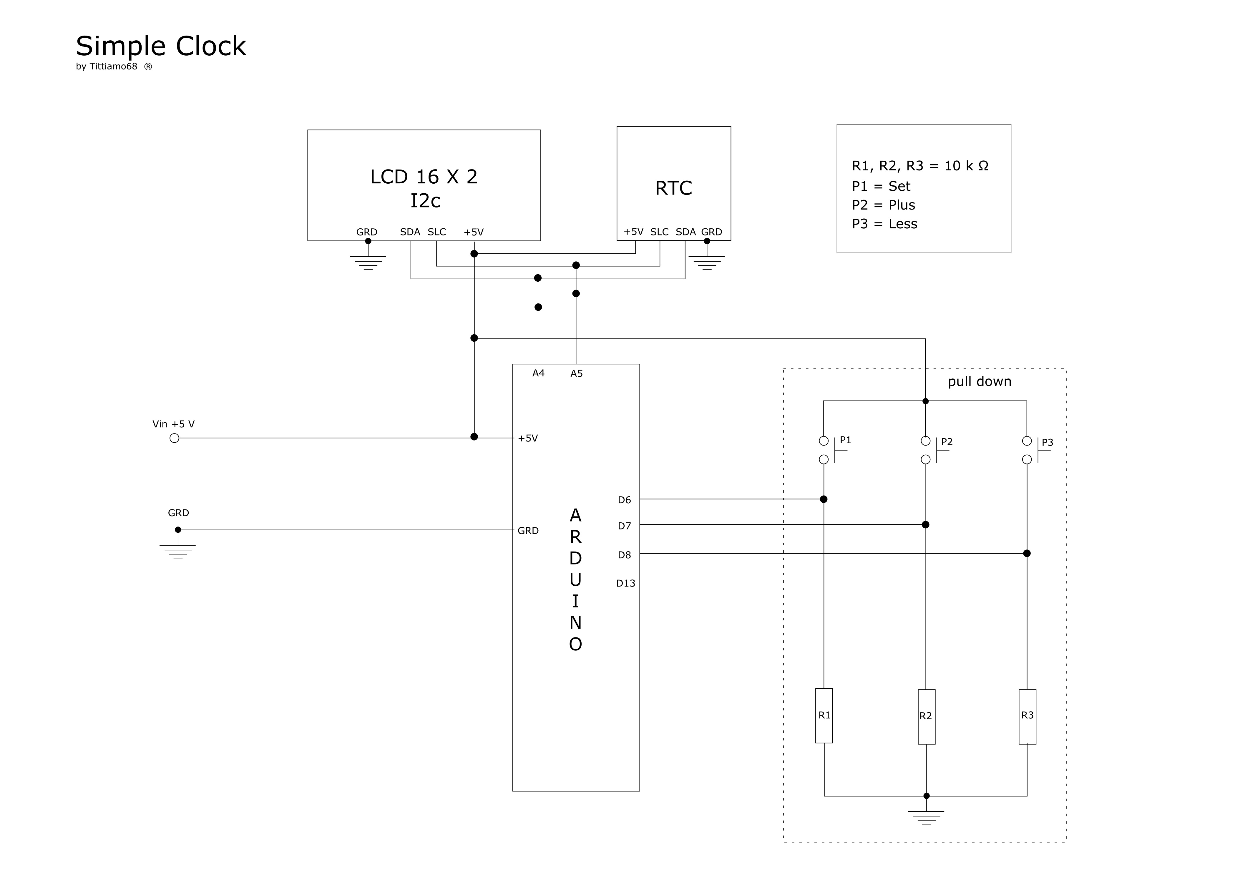
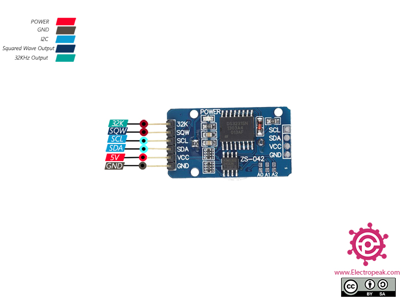
The LCD display comes with no connector by default. Also there are many different versions of the 1602 LCD display with different pinouts and I couldn’t really find which the DX version exactly was. This is one of the first things I try with the Arduino, but since I could not find one tutorial that covered the combination of using the LCD screen ánd the light sensor, I decided to write one beginner tutorial. a project using a DS3231 RTC module, a 16×2 I2C LCD and an Arduino Uno. I am using only parts from the Arduino starter kit I got from Deal Extreme. An Arduino Tutorial about timekeeping, what is a DS3231 real-time clock module.
#Lcd ds3231 arduino uno pinout how to#
These parts don't exist on Fritzing so I didn't make the schematic.This tutorial shows how to connect the 1602A LCD display and a light sensor to your Arduino (UNO) and display the light intensity on the screen. The LCD screen blinks when the time changes.
#Lcd ds3231 arduino uno pinout code#
I see a (0h) code in the code so I guess it has something to do with that. The time I set on the clock reset to zero here. I have previously used a Set Time sketch to set the time and date for a basic RTC sketch, but it didn't work here.

Start by connecting VIN pin to the 5V output on the Arduino and connect GND to ground. You only need to connect 4 pins instead of 12. It is much easier to connect an I2C LCD than to connect a standard LCD.

This whole process made me realize that I need to start paying more attention to the Arduino code and start learning it. Hooking up an Arduino Uno to an I2C LCD display. The code worked so I decided to publish this as my second project. After about 5 weeks I came across a YouTube video and visited the links provided. I tried many sites and different code but I couldn't get it to work. I wanted to be able to do a basic thing like print the time and date on a 1602 LCD i2C screen. I bought a Keyestudio starter kit and I couldn't get Project 31: DS1302 Real Time Clock Module to work so I tried using a RTC DS3231. I have only been using Arduino for about 2 months now.


 0 kommentar(er)
